
Direct answer
What is the product feed system on a filling machine?
The product feed system is the complete route that receives product from the agreed source, conditions it where necessary and supplies the dosing element without starvation, uncontrolled pressure, air, segregation or temperature drift. It can include a hopper or balance tank, transfer pump, hoses or pipework, filters, level devices, agitation, heating, recirculation, isolation, drainage and controls.
- Define the source-to-nozzle boundary before the machine is quoted.
- Keep the product condition at the filler inlet inside an agreed operating range.
- Size refill and transfer around sustainable production, not only the average consumption.
- Plan product recovery, drainage and cleaning at the same time as supply.
- Test start-up, low level, refill, blocked and end-of-batch states.
Draw the boundary from source vessel to filling nozzle
Begin with a simple process sketch. Identify where Lancing’s supply scope starts, where the customer’s product ends and which party provides each vessel, pump, hose, valve, sensor and control signal. Include vertical height, route length, line size, connections, mobile equipment and any change in elevation. A product sample alone cannot show whether the installed filler will be starved or over-pressurised.
The boundary should also state who controls refill, what happens when the source becomes empty, how a new batch is connected and how the line is made safe for cleaning or maintenance. These interfaces belong in the user requirement specification and acceptance tests.
Compare common product-feed arrangements
| Arrangement | Where it may fit | Questions to resolve |
|---|---|---|
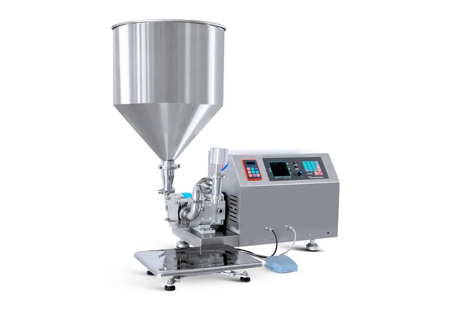
| Machine-mounted hopper | Short product path, operator-fed batches, many paste or piston applications. | Refill height, useful volume, level variation, agitation, heating, covers, drainage and cleaning. |
| Local balance or day tank | Automatic lines needing a controlled level close to the filler. | Refill logic, high/low limits, overflow, venting, cleaning, batch separation and source-pump control. |
| Remote vessel with transfer pump | Bulk batches or existing process plant feeding the line. | Suction conditions, pump type, pressure control, pipe losses, air ingress, isolation and ownership of controls. |
| IBC, drum or mobile vessel transfer | Campaign production, contract packing or products delivered in bulk packs. | Connection standard, lifting or handling, empty detection, residual recovery, closed transfer and changeover. |
| Powder or granule hopper and feeder | Auger, cup or weigh dosing of dry products. | Bulk density, bridging, dust, compaction, segregation, hopper level and refill disturbance. |
Control pressure, head and prime at the dosing element
The same filler can behave differently when its inlet condition changes. A gravity-fed piston may refill more slowly as the hopper empties. A suction pump may draw air through a loose connection. A transfer pump can over-pressurise a valve designed for flooded suction. A long flexible hose can expand and release stored product after the stop command.
Define the permitted inlet pressure or level range for the proposed dosing system. Include check valves, pressure relief or regulation only where the application and design require them. During trials, observe the first dose after priming, steady running, the lowest normal level and the response after a refill or pause.
Use agitation and temperature control only to maintain the required product condition
Agitation can keep particles suspended, prevent phase separation or equalise temperature, but it can also entrain air, increase shear or damage inclusions. Heating can reduce viscosity, yet it changes density, product stability, hose behaviour and operator hazards. The intended speed, direction, duration and control method should therefore be based on the actual product and process rather than a generic “agitator required” note.
State whether the filler receives product already conditioned, whether the machine hopper must maintain that condition, and how temperature or agitation will be monitored. For hot products, align the feed design with the hot-fill process and pack requirements.
Design refill logic so replenishment does not disturb dosing
A high and low level signal can start and stop a transfer pump, but the switching band, sensor principle and refill rate must suit the product. A violent refill can create bubbles or disturb suspended solids. A slow refill can starve several filling heads. Foam or coating on the sensor can also affect level detection.
Define the normal working level, alarm limits, refill source, pump response and the action if the level does not recover. For multi-head lines, confirm that the source can supply the combined peak demand rather than only the average hourly volume.
Review recirculation as a product process, not a default feature
Recirculation may maintain temperature, suspension or line readiness, but it can also introduce heat, air, shear or excessive residence time. Map where the return enters, how it affects the local tank and what happens while filling is stopped. If rejected or overfilled product is returned, define whether that route is permitted and how contamination or traceability is controlled.
Dry-product feeding depends on bulk behaviour and hopper history
For powders and granules, the feed system establishes the condition presented to an auger, cup or weigh feeder. Hopper level, refill drop height, vibration and agitation can change compaction or segregation. Bridging or ratholing can starve the dosing element even when the hopper appears full. Dust extraction and safe product handling may also be part of the cell.
Use production-representative material and repeat the trial after a hopper refill. The powder filling guide and auger filler page cover the downstream dosing decisions.
Plan recovery, emptying and cleaning before fixing the pipework
Product left in a hopper, hose or return line affects yield, changeover time and cleaning burden. Provide drain points, removable connections and access where the selected cleaning method requires them. Avoid creating low points or dead legs that cannot be emptied or verified. If clean-in-place is proposed, confirm that every component is designed for the cleaning flow, temperature, chemistry and drainage route.
The clean-in-place guide helps define the boundary, while the cleaning and changeover guide covers release of the next production run.
Integrate feed controls with filler and line states
The product source should respond safely when the filler is starved, blocked, stopped, faulted or isolated. Signals may include permission to feed, low-level demand, high-level stop, pump fault, temperature ready and clean status. Define fail-safe states and manual recovery. A transfer pump that continues running against a closed path can create a different risk from a filler that simply stops dosing.
Record these interfaces in the line controls schedule and test them during FAT or SAT. The controls and data guide provides a framework for line states and signal ownership.
Product-feed information to include in an enquiry
- Product description, safety data and representative sample.
- Batch size, source vessel, normal minimum and maximum level.
- Viscosity, temperature, density, foam, air, solids and separation behaviour.
- Existing transfer pump, pipe or hose details and connection standard.
- Required agitation, heating, recirculation, filtration or closed transfer.
- Distance, height and available floor space between source and filler.
- Refill method, operator tasks and expected production pattern.
- Recovery, drainage, cleaning and changeover requirements.
- Signals, alarms, interlocks and responsibility at each interface.